glsl functions
Explore GLSL functions through distances and repeating patterns.
Continues hello shaders.
GLSL stands for OpenGL Shading Language.
Setup
Same p5 setup as the previous part, the online editor works just as well.
<link rel="stylesheet" href="/demo/reset.css">
<script src="https://cdn.jsdelivr.net/npm/p5@2.3.0/lib/p5.min.js"></script>
Same runner:
async function setup(){
  createCanvas(200,200, WEBGL)
    myShader = await loadShader("shader.vert", "shader.frag")
}

function draw(){
  shader(myShader)
  rect(-width/2, -height/2, width,height)
}
And the same two GLSL files:
#version 300 es
precision mediump float;

in vec3 aPosition;
out vec2 vPos;

void main(){
  vec4 position = vec4(aPosition, 1.0);
  position.xy = position.xy * 2.0 - 1.0;
  vPos = position.xy;
  gl_Position = position;
}
#version 300 es
precision mediump float;

in vec2 vPos;
out vec4 fragColor;

void main(){
 fragColor = vec4(1.0, 1.0, .0, 1.0);
}
Let's start
Let's begin with what we already have: the position of each fragment, painted as grey.
void main(){
+ float x = vPos.x;
+ float y = vPos.y;
- fragColor = vec4(1.0, 1.0, .0, 1.0);
+ fragColor = vec4(x, x, x, 1.0);
}
- fragColor = vec4(x, x, x, 1.0);
+ fragColor = vec4(y, y, y, 1.0);
It isn't a strictly accurate picture, everything below zero clamps to black, but it makes the point: x runs left to right, y runs bottom to top, 0.0 is black and 1.0 is white. Like math class, and unlike the screen coordinates you're used to in JS.
length(vec)
length(vec) returns the distance of a vector from the origin, the centre of our coordinate space.
void main(){
- float x = vPos.x;
- float y = vPos.y;
- fragColor = vec4(y, y, y, 1.0);
+ vec2 uv = vPos;
+ float d = length(uv);
+ fragColor = vec4(d, d, d, 1.0);
}
In GLSL a scalar applies to the whole vector, so subtracting 0.5 moves both components at once, and the dark centre moves with them:
- vec2 uv = vPos;
+ vec2 uv = vPos - 0.5;
So far we've been fetching the fragment position the long way around: the CPU hands the square's vertices to the vertex shader, we pass them out as vPos, and the fragment shader reads them back in. That was a good way to watch data travel down the pipeline, but for reading screen position, none of it is necessary.
The GPU already knows where each fragment lives, and it hands us the coordinate in a built-in variable: gl_FragCoord.
To see where that number comes from, look at the stage called rasterization, the step that turns a shape into the 2D grid of pixels that ends up on the screen.
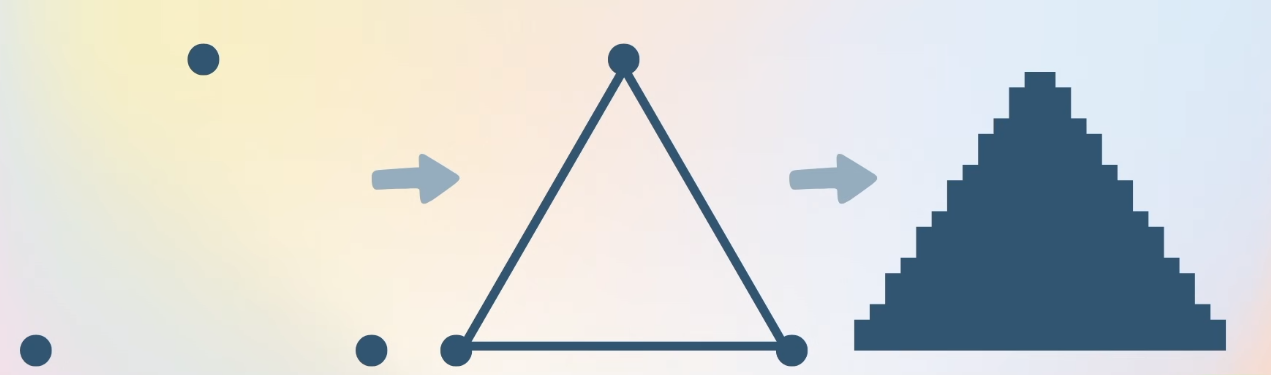
So in shader.frag we drop vPos and use gl_FragCoord instead:
- in vec2 vPos;
out vec4 fragColor;

void main(){
- vec2 uv = vPos - 0.5;
+ vec2 uv = gl_FragCoord.xy - 0.5;
Everything is white, and the reason is the range: vPos arrived between 0 and 1, while gl_FragCoord is measured in pixels, 0 to 200 on our canvas. Past 1.0 every channel clamps to white.
So we need to normalize it, which means the shader has to know the canvas size. We send it from the CPU as a uniform:
function draw(){
-  shader(myShader)
+  shader(myShader)
+  myShader.setUniform('uResolution',[width,height])
#version 300 es
precision mediump float;

out vec4 fragColor;
uniform vec2 uResolution;

void main(){
vec2 uv = (gl_FragCoord.xy/uResolution.xy) - 0.5;
float d = length(uv);
fragColor = vec4(d, d, d, 1.0);
}
If the circle isn't centred on your screen, you probably have a high-DPI display: the drawing buffer is larger than width/height, so the division doesn't land where we expect. Add pixelDensity(1) to p5's setup().
async function setup(){
  createCanvas(200,200, WEBGL)
  myShader = await loadShader("shader.vert", "shader.frag")
  pixelDensity(1)
}

function draw(){
   shader(myShader)
   myShader.setUniform('uResolution',[width,height])
  rect(-width/2, -height/2, width,height)
}
Now, how do we make an effect that repeats? Meet fract().
fract()
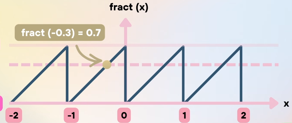
fract() strips the whole part and leaves the fraction: fract(11.2) == 0.2. You'd expect fract(-11.4) == -0.4, but that's not what happens, the actual definition is fract(x) = x - floor(x):
fract(-0.3)=-0.3 - floor(-0.3)
= -0.3 - (-1.0)
= 0.7
So the function always climbs from 0 to 1 and starts over, negative numbers included, a free repeating ramp.
#version 300 es
precision mediump float;

out vec4 fragColor;
uniform vec2 uResolution;

void main(){
vec2 uv = (gl_FragCoord.xy/uResolution.xy) - 0.5;
uv = fract(uv);
float d = length(uv);
fragColor = vec4(d, d, d, 1.0);
}
The seam comes from that wrap-around: on the left edge fract(-0.5) is 0.5, and just before the origin fract(-0.001) is 0.999. On the positive side the ramp grows normally.
Multiply before wrapping and we get more cells:
- uv = fract(uv);
+ uv = fract(uv * 2.0);
Subtracting 0.5 after the wrap re-centres each cell:
- uv = fract(uv);
+ uv = fract(uv * 2.0) -0.5;
Multiply the range by 3.0:
- uv = fract(uv);
+ uv = fract(uv * 3.0) -0.5;
By 4.0:
- uv = fract(uv);
+ uv = fract(uv * 4.0) -0.5;
By 5.0:
- uv = fract(uv);
+ uv = fract(uv * 5.0) -0.5;
- uv = fract(uv);
+ uv = fract(uv * 3.0) - 0.5;
Back to three cells. Now what happens if I stretch the canvas to 600×200?
async function setup(){
-  createCanvas(200,200, WEBGL)
+  createCanvas(600,200, WEBGL)
The cells stretch with it. Dividing by the resolution maps each axis to 0–1 no matter how many pixels it holds, so one unit on x is now three times wider than one unit on y. The fix is to correct for the aspect ratio:
- vec2 uv = (gl_FragCoord.xy/uResolution.xy) - 0.5;
+ vec2 uv = (gl_FragCoord.xy/uResolution.xy);
+ uv.x *= uResolution.x / uResolution.y;
Multiplying x back by width / height restores square units: y still runs 0 to 1, while x runs 0 to the aspect ratio, 3.0 on a 600×200 canvas. Circles are round again, and the wider axis simply fits more of them.
One last thing. Open almost any example on shadertoy and you'll meet a line like this:
vec2 uv = (fragCoord * 2.0 - iResolution.xy) / iResolution.y;
Nothing new is hiding in there, we've already written its cousin in shader.vert:
position.xy = position.xy * 2.0 - 1.0;
Same trick, different input range. In the vertex shader the values arrive between 0 and 1, so multiplying by 2 and subtracting 1 maps them to −1…1.
In the fragment shader gl_FragCoord runs from 0 to the canvas width and 0 to the canvas height. Multiplying by 2 and subtracting the resolution gives -width…width and -height…height; dividing both by the height then gives y a clean −1…1 and x a range of -w/h…w/h, the aspect ratio correction baked into the same expression.
Comments & reactions
Sign in with GitHub to join the conversation.
Comments load as you reach this section.